Autolaturi mökille varavoimaksi Arduinon avulla

Näköjään oli vielä debuggaus vähän vaiheessa! ;)

Eli tuo koodi on siltä osin rikki (poistin servokoodin kokonaan testiksi), että PWM toimii vain ensimmäisellä syklillä. Syklillä tarkoitan WAITING-tilasta takaisin WAITING-tilaan. Eli toisella kierroksella PWM-pinni menee pimeäksi. Jostain tulee nyt toisella kierroksella käsky PWM-pinniin sulkeutua, heti siis RAMP-UP tilasta alkaen.

PWM-pinniin tulee eloa vasta sammutus-funktiossa, jossa siihen ihan oikein tulee se, mitä koodissa on, eli se 15. Sitten lopuksin ajastimen tullessa maaliin, ajetaan taas 255. Koodina siis kyseessä se, johon ei koskaan ole lisätty servoa mukaan. En vain näköjään ollut sitä koodia näin testannutkaan. Servo-koodin kanssa PWM-pinni tosin pimenee heti ekalla kierroksella.

C++:
#include <Wire.h>
#include <LiquidCrystal_I2C.h>
#include <neotimer.h>

// System status variables
#define WAITING 0
#define STARTING 1
#define STARTED 2
#define RAMP_UP 3
#define RUNNING 4
#define FAIL 5

// Fail state LCD display
#define FAILED_START 1
#define OVERVOLTAGE 2
#define FAILED_RPM 3
#define FAILED_VIBSENSOR 4

// Pin definitions
const int currentPin = A0;
const int voltagePin = A3;
const int motorPin = 2;
const int pwmPin = 9;
const int relayPin = 4;
const int rpmPin = 11;
const int overPin = 12;
const int starterPin = 3;

// Timers
Neotimer motorTime = Neotimer(10000);    // 10 seconds for startup detection
Neotimer stepTime = Neotimer(1000);      // 1 second for PWM step interval
Neotimer shutTime = Neotimer(15000);     // 15 seconds for engine shutdown
Neotimer crankTime = Neotimer(4000);     // 4 seconds for cranking
Neotimer crankWait = Neotimer(5000);     // 5 seconds wait after failed crank
Neotimer voltageWait = Neotimer(10000);  // 10 seconds wait for undervoltage
Neotimer sensorTime = Neotimer(5000);    // 5 seconds check time for vibration sensor condition on RUNNNING status
Neotimer buttonTime = Neotimer(2000);    // 2 seconds charging button timer, bypass voltage waiting
Neotimer currentReadTimer = Neotimer(40); // 40 ms for current readings (40msx25=1000 ms update)
Neotimer voltageReadTimer = Neotimer(40); // 40 ms for voltage readings (40msx25=1000 ms update)

// LCD
LiquidCrystal_I2C lcd(0x27, 16, 2);

// Variables
int motorStatus = WAITING;
int startTry = 0;
int startInterval = 0;  // Waiting time on after start attempt
int currentPwmStep = 0;
int pwmValues[] = { 15, 53, 91, 129 };  // PWM steps
int lcdFail = 0;                        // LCD fail state display

// Current and voltage calculation
float voltageFactor = 5.00 / 1023.00;  // Factor to convert ADC reading to voltage

// Define the points for current calculation / the line equation
float x1 = 0.500;  // volts
float y1 = 0;      // amps
float x2 = 4.300;  // volts
float y2 = 150;    // amps
// Calculate the slope and intercept
float m = (y2 - y1) / (x2 - x1);
float b = y1 - m * x1;

float currentCal = 1;  // Variable to shift the whole current level

float sensVfactor = 20.00 / 4.9197;  // 4.9197 volts = 20 volts, factor to convert high voltage to 0-5 V
const int N = 25;                    // Number of current readings to average
const int Y = 25;                    // Number of sensed voltage readings to average
int readings[N];                     // Array to store the current readings
int readingsV[Y];                    // Array to store the sensed voltage readings

// Step counters for readings
int currentReadStep = 0;
int voltageReadStep = 0;

float sensVoltage = 12.0;  // Example voltage
float current = 0.0;       // Example current

//RPM Calculation
unsigned long rpm = 0;   // int rpm = 0;
unsigned long duration;  // Sensor pulse in duration

void setup() {

  Serial.begin(250000);

  // Change timers on pins to change PWM freq to 122 Hz
  // Pins D9 and D10 - 122 Hz
  TCCR1A = 0b00000001;  // 8bit
  TCCR1B = 0b00000100;  // x256 phase correct

  // Initialize I2C and check if LCD is connected
  Wire.begin();
  Wire.beginTransmission(0x27);
  if (Wire.endTransmission() == 0) {
    // LCD is connected, proceed with initialization
    lcd.begin(16, 2);
    lcd.backlight();
    lcd.clear();
  } else {
    // LCD is not connected, continue without initializing the LCD
    Serial.println("LCD not connected. Skipping.");
  }

  // Pin modes
  pinMode(currentPin, INPUT);
  pinMode(voltagePin, INPUT);
  pinMode(motorPin, INPUT_PULLUP);
  pinMode(pwmPin, OUTPUT);
  pinMode(relayPin, OUTPUT);
  pinMode(rpmPin, INPUT_PULLUP);
  pinMode(overPin, INPUT_PULLUP);
  pinMode(starterPin, OUTPUT);

  analogWrite(pwmPin, 255);  // Start with PWM off
}

void startCharge() { // Start charging without to wait lower voltage, bypass voltage time
  if (digitalRead(overPin) == LOW) {
    if (!buttonTime.started()) {
      buttonTime.start();
    }
    if (buttonTime.done()) {
      motorStatus = STARTING;
      digitalWrite(relayPin, HIGH);  // Relay on
      buttonTime.stop();
      buttonTime.reset();
    }
  } else {
    buttonTime.stop();
    buttonTime.reset();
  }
}

void motorCrankState() {
  if (sensVoltage < 1.9) {
    if (!voltageWait.started()) {
      voltageWait.start();
    }
    if (voltageWait.done()) {
      motorStatus = STARTING;
      digitalWrite(relayPin, HIGH);  // Relay on
      voltageWait.stop();
      voltageWait.reset();
    }
  } else {
    voltageWait.stop();
    voltageWait.reset();
  }
}

void crank() {
  if (startTry < 5 && startInterval == 0) {
    if (rpm <= 300) {  // If motor runs slower than this, switch starter relay on
      digitalWrite(starterPin, HIGH);
      if (!crankTime.started()) {
        crankTime.start();
      }
      if (crankTime.done()) {  // If max cranking time finished without succeeding start, switch starter relay off
        digitalWrite(starterPin, LOW);
        crankTime.stop();
        crankTime.reset();
        startTry++;
        startInterval = 1;
      }
    } else if (rpm > 300) {  // If motor runs faster than this, switch starter relay off
      digitalWrite(starterPin, LOW);
      startTry = 0;
      motorStatus = STARTED;
      crankTime.stop();
      crankTime.reset();
    }
  }
}

void Waiter() {
  if (startInterval == 1) {
    if (!crankWait.started()) {
      crankWait.start();
    }
    if (crankWait.done()) {
      startInterval = 0;
      crankWait.stop();
      crankWait.reset();
    }
  }
}

void motorRunning() {
  if (rpm > 1800 || digitalRead(motorPin) == HIGH) {
    if (!motorTime.started()) {
      motorTime.start();
    }
    if (motorTime.done()) {
      motorStatus = RAMP_UP;
      motorTime.stop();
      motorTime.reset();
    }
  }
}

void rampUp() {
  if (stepTime.repeat()) {
    analogWrite(pwmPin, pwmValues[currentPwmStep]);
    currentPwmStep++;
    if (currentPwmStep >= sizeof(pwmValues) / sizeof(pwmValues[0])) {
      motorStatus = RUNNING;
      stepTime.stop();
      stepTime.reset();
    }
  }
}

void shutDown() {
  if (current < 5) {
    digitalWrite(relayPin, LOW);  // Turn off the ignition relay
    analogWrite(pwmPin, 15);      // Set PWM to 5% (reduce alternator load)

    if (!shutTime.started()) {
      shutTime.start();  // Start the shutdown timer
    }

    if (shutTime.done()) {
      analogWrite(pwmPin, 255);  // Set PWM to 100% (alternator electromagnet off)
      motorStatus = WAITING;     // Revert to WAITING state
      shutTime.stop();           // Stop the timer
      shutTime.reset();          // Reset the timer
    }
  }
}

void failState() {  // Handle failed start attempts, overvoltage etc.

  if (startTry == 5) {  // Failed start
    motorStatus = FAIL;
    digitalWrite(starterPin, LOW);  // Starter relay off
    digitalWrite(relayPin, LOW);    // Ignition switch relay off
    lcdFail = FAILED_START;

  } else if (sensVoltage >= 15) {  // Overvoltage
    motorStatus = FAIL;
    digitalWrite(relayPin, LOW);  // Ignition relay off
    lcdFail = OVERVOLTAGE;

    if (!shutTime.started()) {
      shutTime.start();  // Start the shutdown timer
    }

    if (shutTime.done()) {
      analogWrite(pwmPin, 255);  // Set PWM to 100% (alternator electromagnet off)
      shutTime.stop();           // Stop the timer
      shutTime.reset();          // Reset the timer
    }

  } else if ((rpm <= 900 || rpm >= 3700) && motorStatus == RUNNING) {  // RPM sensor
    motorStatus = FAIL;
    digitalWrite(relayPin, LOW);  // Ignition relay off
    lcdFail = FAILED_RPM;

    if (!shutTime.started()) {
      shutTime.start();  // Start the shutdown timer
    }

    if (shutTime.done()) {
      analogWrite(pwmPin, 255);  // Set PWM to 100% (alternator electromagnet off)
      shutTime.stop();           // Stop the timer
      shutTime.reset();          // Reset the timer
    }

    //  } else if (motorStatus == RUNNING) { // Vibration sensor
    //    if (digitalRead(motorPin) == LOW) {
    //      if (!sensorTime.started()) {
    //        sensorTime.start();  // Start the sensor blackout timer
    //      }

    //      if (sensorTime.done()) {
    //        motorStatus = FAIL;
    //        analogWrite(pwmPin, 15);

    //        lcd.setCursor(0, 0);  // On lcd print "Faulty vibration signal"
    //        lcd.print("Virheellinen");
    //        lcd.setCursor(0, 1);
    //        lcd.print("V");
    //        lcd.print((char)0xe1);
    //        lcd.print("rin");
    //        lcd.print((char)0xe1);
    //        lcd.print("signaali");
    //        lcd.print("  ");

    //        sensorTime.stop();
    //        sensorTime.reset();
    //      }

    //    } else {  // If signal reverts to normal during the time, stop timer
    //      sensorTime.stop();
    //      sensorTime.reset();
  }
}
//}


void lcdDisplay() {
  if (motorStatus == RUNNING || motorStatus == RAMP_UP) {
    lcd.setCursor(0, 0);
    lcd.print("Virta:   ");
    lcd.print(current);
    lcd.print(" A ");
    lcd.setCursor(0, 1);
    lcd.print("J");
    lcd.print((char)0xe1);
    lcd.print("nnite: ");
    lcd.print(sensVoltage);
    lcd.print(" V ");

  } else if (motorStatus == WAITING) {
    lcd.setCursor(0, 0);
    lcd.print("Odottaa...      ");
    lcd.setCursor(0, 1);
    lcd.print("J");
    lcd.print((char)0xe1);
    lcd.print("nnite: ");
    lcd.print(sensVoltage);
    lcd.print(" V ");

  } else if (motorStatus == STARTING || motorStatus == STARTED) {
    lcd.setCursor(0, 0);
    lcd.print("K");
    lcd.print((char)0xe1);
    lcd.print("ynnistet");
    lcd.print((char)0xe1);
    lcd.print((char)0xe1);
    lcd.print("n");
    lcd.setCursor(0, 1);
    lcd.print("................");

  } else if (lcdFail == FAILED_START) {
    lcd.setCursor(0, 0);  // On lcd print "Engine start failed"
    lcd.print("K");
    lcd.print((char)0xe1);
    lcd.print("ynnistys      ");
    lcd.setCursor(0, 1);
    lcd.print("ep");
    lcd.print((char)0xe1);
    lcd.print("onnistui     ");

  } else if (lcdFail == OVERVOLTAGE) {
    lcd.setCursor(0, 0);  // On lcd print "Overvoltage"
    lcd.print("Ylij");
    lcd.print((char)0xe1);
    lcd.print("nnite      ");
    lcd.setCursor(0, 1);
    lcd.print("                ");

  } else if (lcdFail == FAILED_RPM) {
    lcd.setCursor(0, 0);  // On lcd print "Faulty rpm"
    lcd.print("Kierrosluku     ");
    lcd.setCursor(0, 1);
    lcd.print("virheellinen    ");
  }
}

void loop() {

  // Calculate current from sensor reading
  if (currentReadStep < N) {
    if (currentReadTimer.repeat()) {
      readings[currentReadStep] = analogRead(currentPin);
      currentReadStep++;
    }
  } else {
    // Calculate the average of the N readings
    float sum = 0;
    for (int i = 0; i < N; i++) {
      sum += readings[i];
    }
    float average = sum / N;
    float voltage = average * voltageFactor;
    current = (m * voltage + b) * currentCal;
    currentReadStep = 0;
  }

  // Calculate high voltage from voltage divider input
  if (voltageReadStep < Y) {
    if (voltageReadTimer.repeat()) {
      readingsV[voltageReadStep] = analogRead(voltagePin);
      voltageReadStep++;
    }
  } else {
    // Calculate the average of the Y readings
    float sumV = 0;
    for (int j = 0; j < Y; j++) {
      sumV += readingsV[j];
    }
    float averageV = sumV / Y;
    float voltageV = averageV * voltageFactor;
    sensVoltage = voltageV * sensVfactor;
    voltageReadStep = 0;
  }

  // RPM Calculation from Hall Sensor input
  // {
  // duration = pulseIn(rpmPin, FALLING, 500000);  // Times the amount of microseconds the motor is not timing IR, Times out after 100000 uS. Raise the timeout for slower RPM readings. .5 second
  // rpm = 60000.0 / duration * 1000;              // See above
  // }

  // Simulate sensor readings via Serial input
  if (Serial.available() > 0) {
    char input = Serial.read();

    switch (input) {
      case '1':
        rpm = 0;
        break;
      case '2':
        rpm = 500;
        break;
      case '3':
        rpm = 2000;
        break;
      case 'a':
        current = 2;
        break;
      case 'b':
        current = 20;
        break;
      case 'c':
        current = 80;
        break;
      case 'z':
        sensVoltage = 11;
        break;
      case 'x':
        sensVoltage = 14;
        break;
      case 'y':
        sensVoltage = 16;
        break;
      default:
        Serial.println("Invalid input.");
        return;
    }
  }

  // Handle motor status
  switch (motorStatus) {
    case WAITING:
      motorCrankState();
      startCharge();
      break;
    case STARTING:
      crank();
      Waiter();
      break;
    case STARTED:
      motorRunning();
      break;
    case RAMP_UP:
      rampUp();
      break;
    case RUNNING:
      shutDown();
      break;
  }

  lcdDisplay();
  failState();

  // Debug output
  Serial.print("Voltage: ");
  Serial.print(sensVoltage);
  Serial.print(" V, Current: ");
  Serial.print(current);
  Serial.print(" A, RPM: ");
  Serial.print(rpm);
  Serial.print(", Status: ");
  Serial.print(motorStatus);
  Serial.print(", Start try: ");
  Serial.print(startTry);
  Serial.print(", Start wait: ");
  Serial.println(startInterval);
}
 
Laitan tähän uuden viestin, koska tulee muuten niin pitkiä litanioita, ettei niitä kukaan jaksa lukea.

Eli löysin ainakin muutamia ongelmia tuosta ja vielä kerrattuna muuta ongelmaa.

Sammutus. Siinä on pelkkä virtakynnys alle 5 A. Onko niin, että jos tuo viisi ampeeria ylittyykin, kun jo tuota kohtaa on alettu ajamaan, tulee joku tiltti? Nimittäin, kun todellisuuskin on sitä, että se heittelee siinä välttämättä plus-miinus viiden ampeerin. Vai toimiiko ohjelmakoodi niin, että jos tuo luku kerran alittuu, ajetaan funktio loppuun saakka? Simulaattorilla toimi, mutta Arduinolla ei. Se jäi Arduinolla siihen kohtaan, jossa PWM lasketaan 15:een. Ja nyt sain testattua sarjaporttisyötteellä, siitä se johtuu. Eli tilat vaihtuvat hienosti, kun virtakynnys alittuu pysyvästi!!! :O
Ja testattu fyysisesti Arduinolla, virtakynnys homma toimii.

Sitten se isompi ongelma, eli PWM, menee pimeäksi, kun aloitetaan toinen kierros (WAITING-->WAITING jne..).
 
Viimeksi muokattu:
No niin, pahoittelut massapostituksesta, mutta tässä taas uusi koodi. Jonka pitäisi nyt taas vaihteeksi toimia!

Tekoäly älysi siis korjata nämä ongelmat. Tuo PWM-ongelma oli niin yksinkertainen, kuin että currentPwmStep -muuttujaa ei nollattu missään vaiheessa. Yksi rivi sammutusfunktioon ja zädääm.

Nyt tässä taas toimiva koodi joka toimii myös peräkkäisissä sykleissä ja virtakynnys on nyt kunnossa, ettei se enää estä sammutusfunktion läpiviemistä, vaikka virta hyppelehtisi.

Koodi:
#include <Wire.h>
#include <LiquidCrystal_I2C.h>
#include <neotimer.h>

// System status variables
#define WAITING 0
#define STARTING 1
#define STARTED 2
#define RAMP_UP 3
#define RUNNING 4
#define FAIL 5
#define SHUTTING 6

// Fail state LCD display
#define FAILED_START 1
#define OVERVOLTAGE 2
#define FAILED_RPM 3
#define FAILED_VIBSENSOR 4

// Pin definitions
const int currentPin = A0;
const int voltagePin = A3;
const int motorPin = 2;
const int pwmPin = 9;
const int relayPin = 4;
const int rpmPin = 11;
const int overPin = 12;
const int starterPin = 3;

// Timers
Neotimer motorTime = Neotimer(10000);      // 10 seconds for startup detection
Neotimer stepTime = Neotimer(1000);        // 1 second for PWM step interval
Neotimer shutTime = Neotimer(15000);       // 15 seconds for engine shutdown
Neotimer crankTime = Neotimer(4000);       // 4 seconds for cranking
Neotimer crankWait = Neotimer(5000);       // 5 seconds wait after failed crank
Neotimer voltageWait = Neotimer(10000);    // 10 seconds wait for undervoltage
Neotimer sensorTime = Neotimer(5000);      // 5 seconds check time for vibration sensor condition on RUNNNING status
Neotimer buttonTime = Neotimer(2000);      // 2 seconds charging button timer, bypass voltage waiting
Neotimer currentReadTimer = Neotimer(40);  // 40ms for current readings
Neotimer voltageReadTimer = Neotimer(40);  // 40ms for voltage readings

// LCD
LiquidCrystal_I2C lcd(0x27, 16, 2);

// Variables
int motorStatus = WAITING;
int startTry = 0;
int startInterval = 0;  // Waiting time on after start attempt
int currentPwmStep = 0;
int pwmValues[] = { 15, 53, 91, 129 };  // PWM steps
int lcdFail = 0;                        // LCD fail state display

// Current and voltage calculation
float voltageFactor = 5.00 / 1023.00;  // Factor to convert ADC reading to voltage

// Define the points for current calculation / the line equation
float x1 = 0.500;  // volts
float y1 = 0;      // amps
float x2 = 4.300;  // volts
float y2 = 150;    // amps
// Calculate the slope and intercept
float m = (y2 - y1) / (x2 - x1);
float b = y1 - m * x1;

float currentCal = 1;  // Variable to shift the whole current level

float sensVfactor = 20.00 / 4.9197;  // 4.9197 volts = 20 volts, factor to convert high voltage to 0-5 V
const int N = 25;                    // Number of current readings to average
const int Y = 25;                    // Number of sensed voltage readings to average
int readings[N];                     // Array to store the current readings
int readingsV[Y];                    // Array to store the sensed voltage readings

// Step counters for readings
int currentReadStep = 0;
int voltageReadStep = 0;

float sensVoltage = 12.0;  // Example voltage
float current = 0.0;       // Example current

//RPM Calculation
unsigned long rpm = 0;   // int rpm = 0;
unsigned long duration;  // Sensor pulse in duration

void setup() {

  Serial.begin(250000);

  // Change timers on pins to change PWM freq to 122 Hz
  // Pins D9 and D10 - 122 Hz
  TCCR1A = 0b00000001;  // 8bit
  TCCR1B = 0b00000100;  // x256 phase correct

  // Initialize I2C and check if LCD is connected
  Wire.begin();
  Wire.beginTransmission(0x27);
  if (Wire.endTransmission() == 0) {
    // LCD is connected, proceed with initialization
    lcd.begin(16, 2);
    lcd.backlight();
    lcd.clear();
  } else {
    // LCD is not connected, continue without initializing the LCD
    Serial.println("LCD not connected. Skipping.");
  }

  // Pin modes
  pinMode(currentPin, INPUT);
  pinMode(voltagePin, INPUT);
  pinMode(motorPin, INPUT_PULLUP);
  pinMode(pwmPin, OUTPUT);
  pinMode(relayPin, OUTPUT);
  pinMode(rpmPin, INPUT_PULLUP);
  pinMode(overPin, INPUT_PULLUP);
  pinMode(starterPin, OUTPUT);

  analogWrite(pwmPin, 255);  // Start with PWM off
}

void startCharge() {  // Start charging without to wait lower voltage, bypass voltage time
  if (digitalRead(overPin) == LOW) {
    if (!buttonTime.started()) {
      buttonTime.start();
    }
    if (buttonTime.done()) {
      motorStatus = STARTING;
      digitalWrite(relayPin, HIGH);  // Relay on
      buttonTime.stop();
      buttonTime.reset();
    }
  } else {
    buttonTime.stop();
    buttonTime.reset();
  }
}

void motorCrankState() {  // Voltage lower than this executes starting function
  if (sensVoltage < 11.9) {
    if (!voltageWait.started()) {
      voltageWait.start();
    }
    if (voltageWait.done()) {
      motorStatus = STARTING;
      digitalWrite(relayPin, HIGH);  // Relay on
      voltageWait.stop();
      voltageWait.reset();
    }
  } else {
    voltageWait.stop();
    voltageWait.reset();
  }
}

void crank() {  // Starting function
  if (startTry < 5 && startInterval == 0) {
    if (rpm <= 300) {  // If motor runs slower than this, switch starter relay on
      digitalWrite(starterPin, HIGH);
      if (!crankTime.started()) {
        crankTime.start();
      }
      if (crankTime.done()) {  // If max cranking time finished without succeeding start, switch starter relay off
        digitalWrite(starterPin, LOW);
        crankTime.stop();
        crankTime.reset();
        startTry++;
        startInterval = 1;
      }
    } else if (rpm > 300) {  // If motor runs faster than this, switch starter relay off
      digitalWrite(starterPin, LOW);
      startTry = 0;
      motorStatus = STARTED;
      crankTime.stop();
      crankTime.reset();
    }
  }
}

void Waiter() {  // Wait intervals between start attempts
  if (startInterval == 1) {
    if (!crankWait.started()) {
      crankWait.start();
    }
    if (crankWait.done()) {
      startInterval = 0;
      crankWait.stop();
      crankWait.reset();
    }
  }
}

void motorRunning() {  // Assume that motor is running after the time interval
  if (rpm > 1800) {
    if (!motorTime.started()) {
      motorTime.start();
    }
    if (motorTime.done()) {
      motorStatus = RAMP_UP;
      motorTime.stop();
      motorTime.reset();
    }
  }
}

void rampUp() {  // Ramping up PWM
  if (stepTime.repeat()) {
    analogWrite(pwmPin, pwmValues[currentPwmStep]);
    currentPwmStep++;
    if (currentPwmStep >= sizeof(pwmValues) / sizeof(pwmValues[0])) {
      motorStatus = RUNNING;
      stepTime.stop();
      stepTime.reset();
    }
  }
}

void shutDown() {  // Shut down function
  // Execute if current is low OR shutdown is already in progress
  if (current < 5 || motorStatus == SHUTTING) {
    // Only execute initial steps when first entering SHUTTING state
    if (motorStatus != SHUTTING) {
      motorStatus = SHUTTING;
      digitalWrite(relayPin, LOW);  // Turn off the ignition relay
      analogWrite(pwmPin, 15);      // Set PWM to 5% (reduce alternator load)

      if (!shutTime.started()) {
        Serial.print(", sammutusajastin ");
        shutTime.start();  // Start the shutdown timer
        Serial.print(", sammutusajastin kaynnistetty ");
      }
    }

    // Continue monitoring timer until shutdown completes
    if (shutTime.done()) {
      Serial.print(", sammutusajastin valmis ");
      analogWrite(pwmPin, 255);  // Set PWM to 100% (alternator electromagnet off)
      Serial.print(", pwm 255 ");
      motorStatus = WAITING;  // Revert to WAITING state
      currentPwmStep = 0;     // Reset PWM step counter for next RAMP_UP
      shutTime.stop();        // Stop the timer
      shutTime.reset();       // Reset the timer
    }
  }
}

void failState() {  // Handle failed start attempts, overvoltage etc.

  if (startTry == 5) {  // Failed start
    motorStatus = FAIL;
    digitalWrite(starterPin, LOW);  // Starter relay off
    digitalWrite(relayPin, LOW);    // Ignition switch relay off
    lcdFail = FAILED_START;

  } else if (sensVoltage >= 15) {  // Overvoltage
    motorStatus = FAIL;
    digitalWrite(relayPin, LOW);  // Ignition relay off
    lcdFail = OVERVOLTAGE;

    if (!shutTime.started()) {
      shutTime.start();  // Start the shutdown timer
    }

    if (shutTime.done()) {
      analogWrite(pwmPin, 255);  // Set PWM to 100% (alternator electromagnet off)
      shutTime.stop();           // Stop the timer
      shutTime.reset();          // Reset the timer
    }

  } else if ((rpm <= 900 || rpm >= 3700) && ( motorStatus == RUNNING || motorStatus == FAIL )) {  // RPM sensor
    motorStatus = FAIL;
    digitalWrite(relayPin, LOW);  // Ignition relay off
    lcdFail = FAILED_RPM;

    if (!shutTime.started()) {
      shutTime.start();  // Start the shutdown timer
    }

    if (shutTime.done()) {
      analogWrite(pwmPin, 255);  // Set PWM to 100% (alternator electromagnet off)
      shutTime.stop();           // Stop the timer
      shutTime.reset();          // Reset the timer
    }

    //  } else if (motorStatus == RUNNING) { // Vibration sensor
    //    if (digitalRead(motorPin) == LOW) {
    //      if (!sensorTime.started()) {
    //        sensorTime.start();  // Start the sensor blackout timer
    //      }

    //      if (sensorTime.done()) {
    //        motorStatus = FAIL;
    //        analogWrite(pwmPin, 15);

    //        lcd.setCursor(0, 0);  // On lcd print "Faulty vibration signal"
    //        lcd.print("Virheellinen");
    //        lcd.setCursor(0, 1);
    //        lcd.print("V");
    //        lcd.print((char)0xe1);
    //        lcd.print("rin");
    //        lcd.print((char)0xe1);
    //        lcd.print("signaali");
    //        lcd.print("  ");

    //        sensorTime.stop();
    //        sensorTime.reset();
    //      }

    //    } else {  // If signal reverts to normal during the time, stop timer
    //      sensorTime.stop();
    //      sensorTime.reset();
  }
}
//}


void lcdDisplay() {  // LCD display
  if (motorStatus == RUNNING || motorStatus == RAMP_UP) {
    lcd.setCursor(0, 0);
    lcd.print("Virta:   ");
    lcd.print(current);
    lcd.print(" A ");
    lcd.setCursor(0, 1);
    lcd.print("J");
    lcd.print((char)0xe1);
    lcd.print("nnite: ");
    lcd.print(sensVoltage);
    lcd.print(" V ");

  } else if (motorStatus == WAITING) {
    lcd.setCursor(0, 0);
    lcd.print("Odottaa...      ");
    lcd.setCursor(0, 1);
    lcd.print("J");
    lcd.print((char)0xe1);
    lcd.print("nnite: ");
    lcd.print(sensVoltage);
    lcd.print(" V ");

  } else if (motorStatus == STARTING || motorStatus == STARTED) {
    lcd.setCursor(0, 0);
    lcd.print("K");
    lcd.print((char)0xe1);
    lcd.print("ynnistet");
    lcd.print((char)0xe1);
    lcd.print((char)0xe1);
    lcd.print("n");
    lcd.setCursor(0, 1);
    lcd.print("................");

  } else if (lcdFail == FAILED_START) {
    lcd.setCursor(0, 0);  // On lcd print "Engine start failed"
    lcd.print("K");
    lcd.print((char)0xe1);
    lcd.print("ynnistys      ");
    lcd.setCursor(0, 1);
    lcd.print("ep");
    lcd.print((char)0xe1);
    lcd.print("onnistui     ");

  } else if (lcdFail == OVERVOLTAGE) {
    lcd.setCursor(0, 0);  // On lcd print "Overvoltage"
    lcd.print("Ylij");
    lcd.print((char)0xe1);
    lcd.print("nnite      ");
    lcd.setCursor(0, 1);
    lcd.print("                ");

  } else if (lcdFail == FAILED_RPM) {
    lcd.setCursor(0, 0);  // On lcd print "Faulty rpm"
    lcd.print("Kierrosluku     ");
    lcd.setCursor(0, 1);
    lcd.print("virheellinen    ");
  }
}

void loop() {

  // Calculate current from sensor reading
  if (currentReadStep < N) {
    if (currentReadTimer.repeat()) {
      readings[currentReadStep] = analogRead(currentPin);
      currentReadStep++;
    }
  } else {
    // Calculate the average of the N readings
    float sum = 0;
    for (int i = 0; i < N; i++) {
      sum += readings[i];
    }
    float average = sum / N;
    float voltage = average * voltageFactor;
    current = (m * voltage + b) * currentCal;
    currentReadStep = 0;
  }

  // Calculate high voltage from voltage divider input
  if (voltageReadStep < Y) {
    if (voltageReadTimer.repeat()) {
      readingsV[voltageReadStep] = analogRead(voltagePin);
      voltageReadStep++;
    }
  } else {
    // Calculate the average of the Y readings
    float sumV = 0;
    for (int j = 0; j < Y; j++) {
      sumV += readingsV[j];
    }
    float averageV = sumV / Y;
    float voltageV = averageV * voltageFactor;
    sensVoltage = voltageV * sensVfactor;
    voltageReadStep = 0;
  }

  // RPM Calculation from Hall Sensor input
  // {
  // duration = pulseIn(rpmPin, FALLING, 500000);  // Times the amount of microseconds the motor is not timing IR, Times out after 100000 uS. Raise the timeout for slower RPM readings. .5 second
  //if (duration > 0) {
  // rpm = 60000.0 / duration * 1000;  // See above
  //}
  //}

  // Simulate sensor readings via Serial input
  if (Serial.available() > 0) {
    char input = Serial.read();

    switch (input) {
      case '1':
        rpm = 0;
        break;
      case '2':
        rpm = 500;
        break;
      case '3':
        rpm = 2000;
        break;
      case 'a':
        current = 2;
        break;
      case 'b':
        current = 20;
        break;
      case 'c':
        current = 80;
        break;
      case 'z':
        sensVoltage = 11;
        break;
      case 'x':
        sensVoltage = 14;
        break;
      case 'y':
        sensVoltage = 16;
        break;
      default:
        Serial.println("Invalid input.");
        return;
    }
  }

  // Handle motor status
  switch (motorStatus) {
    case WAITING:
      motorCrankState();
      startCharge();
      break;
    case STARTING:
      crank();
      Waiter();
      break;
    case STARTED:
      motorRunning();
      break;
    case RAMP_UP:
      rampUp();
      break;
    case RUNNING:
      shutDown();
      break;
    case SHUTTING:
      shutDown();
      break;
  }

  lcdDisplay();
  failState();

  // Debug output
  Serial.print("Voltage: ");
  Serial.print(sensVoltage);
  Serial.print(" V, Current: ");
  Serial.print(current);
  Serial.print(" A, RPM: ");
  Serial.print(rpm);
  Serial.print(", Status: ");
  Serial.print(motorStatus);
  Serial.print(", Start try: ");
  Serial.print(startTry);
  Serial.print(", Start wait: ");
  Serial.println(startInterval);
}
 
Laitan tähän uuden viestin, koska tulee muuten niin pitkiä litanioita, ettei niitä kukaan jaksa lukea.

Eli löysin ainakin muutamia ongelmia tuosta ja vielä kerrattuna muuta ongelmaa.

Sammutus. Siinä on pelkkä virtakynnys alle 5 A. Onko niin, että jos tuo viisi ampeeria ylittyykin, kun jo tuota kohtaa on alettu ajamaan, tulee joku tiltti? Nimittäin, kun todellisuuskin on sitä, että se heittelee siinä välttämättä plus-miinus viiden ampeerin. Vai toimiiko ohjelmakoodi niin, että jos tuo luku kerran alittuu, ajetaan funktio loppuun saakka? Simulaattorilla toimi, mutta Arduinolla ei. Se jäi Arduinolla siihen kohtaan, jossa PWM lasketaan 15:een. Ja nyt sain testattua sarjaporttisyötteellä, siitä se johtuu. Eli tilat vaihtuvat hienosti, kun virtakynnys alittuu pysyvästi!!! :O
Ja testattu fyysisesti Arduinolla, virtakynnys homma toimii.

Sitten se isompi ongelma, eli PWM, menee pimeäksi, kun aloitetaan toinen kierros (WAITING-->WAITING jne..).
Koodi:
void shutDown() {
  if (current < 5) {
    digitalWrite(relayPin, LOW);  // Turn off the ignition relay
    analogWrite(pwmPin, 15);      // Set PWM to 5% (reduce alternator load)

    if (!shutTime.started()) {
      shutTime.start();  // Start the shutdown timer
    }

    if (shutTime.done()) {
      analogWrite(pwmPin, 255);  // Set PWM to 100% (alternator electromagnet off)
      motorStatus = WAITING;     // Revert to WAITING state
      shutTime.stop();           // Stop the timer
      shutTime.reset();          // Reset the timer
    }
  }
}

Siis tässä, jos current < 5 testin aikana ehto täyttyy niin koko blokki suoritetaan.
Ja kun tuossa on timer ja sen loppuehto niin saattaa hyvinkin olla että <5 ehto täyttyy tällä kerralla ja seuraavalla kutsulla taas ei jolloin asioita ei enää tehdäkään koska ajastinta ei tarkasteta jne.

Liipaisun ensimmäisestä <5 tilanteesta voi tehdä esimerkiksi jotenkin tähän tyyliin.
Huomaa että <5 ehdossa pitää olla mukana tila, virta- arvo ei kiinnosta ellei olla käynnissä, muuten jää tilat helposti kiertämään kehää sammutuksessa...
Koodi:
uint8_t is_shutting_down = 0;

void shutDown() {
  if ( (current < 5) && ( motorStatus == RUNNING )) {
    is_shutting_down = 1;
  }

  if (is_shutting_down > 0) {
    digitalWrite(relayPin, LOW);  // Turn off the ignition relay
    analogWrite(pwmPin, 15);      // Set PWM to 5% (reduce alternator load)

    if (!shutTime.started()) {
      shutTime.start();  // Start the shutdown timer
    }

    if (shutTime.done()) {
      analogWrite(pwmPin, 255);  // Set PWM to 100% (alternator electromagnet off)
      motorStatus = WAITING;     // Revert to WAITING state
      shutTime.stop();           // Stop the timer
      shutTime.reset();          // Reset the timer
      is_shutting_down = 0;
    }
  }
}
 
Tuo problematiikka tuon servon ja PWM:n kanssa taitaa johtua siitä, että servo-kirjasto käyttää samaa timeria kuin mitä PWM:lle vaaditaan. Kun uudessa versiossa olisi nyt attach ja deattach käytössä, joka käsitykseni mukaan välttää servon jurnuttelua paikallaan. Eli tavallaan irrotetaan servo välillä kokonaan.

Tekoäly ehdottaa tällaista korjaus, onkohan järkevää? Tuleeko pomppua PWM:ään? Eli noissa "käännekohdissa" asetettaisiin timereita aina uudestaan.

Koodi:
// In the STARTING case:
if (!servoMoveTimer.started()) {
  chokeServo.attach(servoPin);
  chokeServo.writeMicroseconds(CHOKE_ON_US);
  // Restore PWM settings after servo attach
  TCCR1A = 0b10000001;  // Non-inverting PWM on OC1A
  TCCR1B = 0b00000100;   // x256 phase correct
  servoMoveTimer.start();
}

// In the STARTED case (choke retraction):
if (!servoMoveTimer.started()) {
  chokeServo.attach(servoPin);
  chokeServo.writeMicroseconds(CHOKE_OFF_US);
  // Restore PWM settings after servo attach
  TCCR1A = 0b10000001;  // Non-inverting PWM on OC1A
  TCCR1B = 0b00000100;   // x256 phase correct
  servoMoveTimer.start();
}

Lisäksi alkuperäinen PWM-asetus, joka siis toimii:

Koodi:
  // Change timers on pins to change PWM freq to 122 Hz
  // Pins D9 and D10 - 122 Hz
  TCCR1A = 0b00000001;  // 8bit
  TCCR1B = 0b00000100;  // x256 phase correct
 
  // Tekoäly haluaisi muuttaa tähän:
  TCCR1A = 0b10000001;  // Non-inverting PWM on OC1A
  TCCR1B = 0b00000100;   // x256 phase correct
 
Viimeksi muokattu:
Tuo problematiikka tuon servon ja PWM:n kanssa taitaa johtua siitä, että servo-kirjasto käyttää samaa timeria kuin mitä PWM:lle vaaditaan. Kun uudessa versiossa olisi nyt attach ja deattach käytössä, joka käsitykseni mukaan välttää servon jurnuttelua paikallaan. Eli tavallaan irrotetaan servo välillä kokonaan.

Tekoäly ehdottaa tällaista korjaus, onkohan järkevää? Tuleeko pomppua PWM:ään? Eli noissa "käännekohdissa" asetettaisiin timereita aina uudestaan.

Koodi:
// In the STARTING case:
if (!servoMoveTimer.started()) {
  chokeServo.attach(servoPin);
  chokeServo.writeMicroseconds(CHOKE_ON_US);
  // Restore PWM settings after servo attach
  TCCR1A = 0b10000001;  // Non-inverting PWM on OC1A
  TCCR1B = 0b00000100;   // x256 phase correct
  servoMoveTimer.start();
}

// In the STARTED case (choke retraction):
if (!servoMoveTimer.started()) {
  chokeServo.attach(servoPin);
  chokeServo.writeMicroseconds(CHOKE_OFF_US);
  // Restore PWM settings after servo attach
  TCCR1A = 0b10000001;  // Non-inverting PWM on OC1A
  TCCR1B = 0b00000100;   // x256 phase correct
  servoMoveTimer.start();
}

Lisäksi alkuperäinen PWM-asetus, joka siis toimii:

Koodi:
  // Change timers on pins to change PWM freq to 122 Hz
  // Pins D9 and D10 - 122 Hz
  TCCR1A = 0b00000001;  // 8bit
  TCCR1B = 0b00000100;  // x256 phase correct
 
  // Tekoäly haluaisi muuttaa tähän:
  TCCR1A = 0b10000001;  // Non-inverting PWM on OC1A
  TCCR1B = 0b00000100;   // x256 phase correct

Pwm keskeytyy/muuttuu aina jos timerin asetuksia muutetaan. Jos signaali pitää olla jatkuva niin ainakaan mode ja taajuus ei saa muuttaa toiminnan aikana.

Atmega 328 siaältää 3 timeria eli kaikille saisi oman. Arduinoframen millis() käyttää timer0:n, sen asetuksia ei saa muuttaa ellei oikeasti tiedä mitä tekee ja mihin kaikkialle vaikuttaa. Sitten 1 ja 2 servolle ja laturin pwm:lle tarpeesta riippuen, niillä kun on vähän eri ominaisuudet.

Timereissa on 2 kanavaa ulos ei yhdellä on mahdollista tuottaa kaksi erilaista pwm- signaalia ulos mutta se ei välttämättä ole ihan helppoa jos taajuudet pitää olla erilaiset.

Ja hyvä yleisohje: jos käytät kirjastoa joka käyttää timeria niin älä koske erikseen timerin asetuksiin kirjaston ulkopuolelta.
 
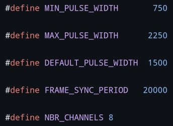
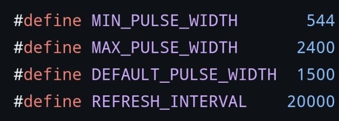
@ississ, Kiitoksia taas. Tuli testattuakin, niin eihän se toiminut, vaan pwm nousee, mutta jää siihen junnaamaan eikä Servo liiku mihinkään. Sinänsä aika helpottava tilanne, että nyt tietää mistä ongelma johtuu.
 
Jos servoa pitää ajaa vain 2 asennon välillä niin eikös tuon pystyisi tekemään millis / micros timerilla ihan manuaalisesti servot about standardoitu missä keski asento ja missä laidat.
löysin esimerkin nopeasti netistä mutta itse lähtisin lähestymään näin niin voi vaikka kertoa tai jakaa pulseja jos ei muuten osu kohdilleen.
tossa joku malli miten tuon onnistuu servoNOlibrary - Wokwi ESP32, STM32, Arduino Simulator
 
Oikeasti helpoin olisi käyttää timer2 käsin servolle.
Delay- virityksissä pitää aina muistaa että kaikki muu seisoo sillä aikaa (paitsi keskeytykset).
Eli voi kunhan sillä aikaa kun servoa liikutetaan ei tarvitse tehdä mitään muuta.
 
@Nasty76 ja @ississ, joo tässä nimenomaan on poistettu kaikki blokkaavat delayt, niin pitäisi tehdä jotenkin muuten tuo sitten. Katsotaan nyt, viitsikö vielä vai mennäänkö solenoidilla.

Ylipäätänsä tässä on rakennellessa huomannut monia asioita, miten olisi kannattanut tehdä. Eihän näitä asioita nähnyt ennen kuin proto alkoi valmistua. Esimerkiksi automaattiryyppy olisi ehdottomasti kannattanut tehdä lineaarimoottorilla. Alkuperäiselle kaasarille se olisi ollut kohtuullisen sujuvakin asentaa siihen moottorin ulkopuolelle. Lineaari moottori on ip-luokiteltu. Ohjaaminen laidasta laitaan kääntämällä vain navat toisinpäin, muutama lisäjohto Rduinolta, yksi lisärele, mutta nyt sitä ei ole enää oikein kohtuudella edes tehdä, koska kotelossakaan ei kerta kaikkiaan ole yhtään tilaa ja siinäpä yksi toinen iso ongelma, että olisi pitänyt valita hyvin suuri kotelo ja kaikki elektroniikka laittaa yhteen isoon koteloon. Myös päävirran olisi voinut tehdä isolla releellä, jota olisi ohjattu pikku kytkemellä, joka olisi myös tullut kotelon pintaan. Paljon vähemmällä olisi päässyt. Mutta eipä siinä, tämähän onkin proto ja nyt on mentävä tällä.
 

Statistiikka

Viestiketjuista
275 041
Viestejä
4 740 639
Jäsenet
77 260
Uusin jäsen
Stupa

Hinta.fi

Back
Ylös Bottom